Introduction

  1. BjnrHLtRJL63iOYL
    BjnrHLtRJL63iOYL
    eSewRhRIKijTfeCI
    TB6C6ZwuyuWap5pv
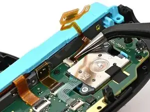
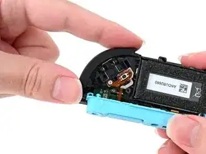
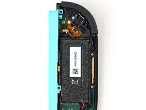
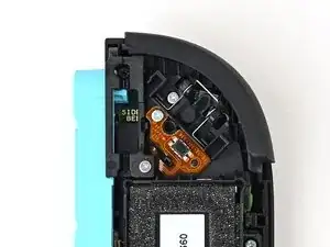
    • Make sure the locking flap is flipped up on the trigger cable's ZIF connector.

    • Position the trigger button board so its ribbon cable is aligned with its ZIF connector on the board.

    • Use tweezers or your fingers to gently slide the ribbon cable into its ZIF connector.

    • Flip the locking flap down to secure the cable.

  2. VKsRDSCkoTLwvwY3
    VKsRDSCkoTLwvwY3
    nCWRqo5ZOIQBxiJK
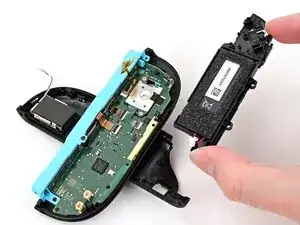
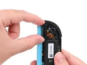
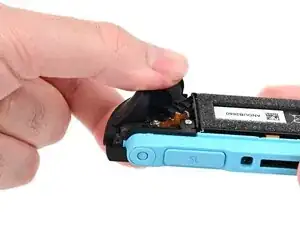
    • Align the midframe with its screw holes on the outer edge of the controller.

  3. pMhP34kY1vYAmvHx
    pMhP34kY1vYAmvHx
    umRbwMogauweEBRH
    5omVI2DOMNArGqAg
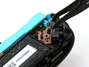
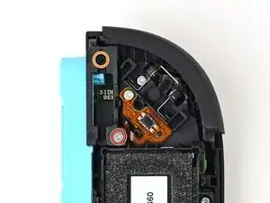
    • Use tweezers or your fingers to set the bottom edge of the trigger button board underneath the tab on the midframe.

    • Press the board into place so the black peg on the midframe protrudes through the hole on the bottom corner of the board.

  4. AdJCiOhToiIYcpXT
    AdJCiOhToiIYcpXT
    MvRrU3wqfGeiXnyx
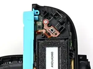
    • Use a JIS 00 driver to install the 3.9 mm‑long silver screw securing the trigger button board.

  5. KOiBNDufxRJla2yE
    KOiBNDufxRJla2yE
    5l2gAwRulSDKCAgg
    2OvUTXTF3oN23qRU
    • Align the two springs on the bumper with their two posts on the midframe, and press it into place.

    • The bumper is held in place by the front shell of the controller. If it falls out, ensure it's fully seated in the shell.

  6. U5p6iQWUuoowiYrR
    U5p6iQWUuoowiYrR
    PxiGGkRkCghDR2UZ
    • Use a JIS 00 driver to install the three 3.9 mm‑long silver screws securing the midframe.

  7. MNnnyO4ltkPifTZm
    MNnnyO4ltkPifTZm
    2eiYDdUytR5Hycv4
    VXCJKIdLhWpW66yR
    • Align the release button bracket with its screw holes and set it in the frame so it snaps into place.

    • The corner with the protruding square should be facing the battery.

  8. fZCPPDstfxYQUPXE
    fZCPPDstfxYQUPXE
    u3QTM5D4drPJhPfx
    • Use a JIS 00 driver to install the two screws securing the release button bracket:

    • One 3.9 mm‑long silver screw

    • One 6.2 mm‑long black screw

  9. xfMpS6NPKDcBq4Tx
    xfMpS6NPKDcBq4Tx
    tWcO6akB6EBCmwcn
    lEeVXBNingcYLB3o
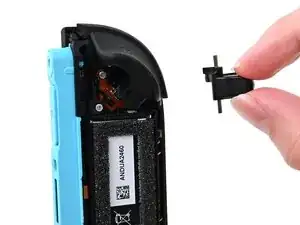
    • Align the trigger button with the top of the controller, with the ZL engraving facing out.

    • Set the trigger button onto its metal spring. Ensure the legs of the metal spring are seated properly in their channels on the midframe.

    • Press firmly on the trigger button to snap it into place.

    • Check that the metal stabilizer didn't fall out of position. If it did, remove the trigger, place it back into position, and try again.

  10. FVZMo4pcLsNOfhQ6
    FVZMo4pcLsNOfhQ6
    hud3AjksMFUi5Jg1
    TmTP5VDhtZZMthO2
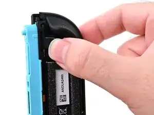
    • Insert the release button into its bracket.

    • If the release pin doesn't stick out of the controller when the button is pressed, the button isn't installed correctly. Re-insert or flip the button and try again.

Conclusion

To reassemble your device, follow these instructions in reverse order.

Nick Schultz

Member since: 24/03/24

37772 Reputation

0 comments